Angle Head
To activate this UDE, the expression that needs to be written in the “Manual NC” operation in Fusion is given below:
ANGLE HEAD/POSITION=@,FREE ANGLE=@
After adding this in Fusion, the following expression will be added to the created APT file as shown below.
GOTO/41., -3., 66.
OPERATION/END
PPRINT/’ANGLE HEAD/POSITION=+X,FREE ANGLE=30’
START/’OPERATION’
MODE/ MILL
The Type of UDE:
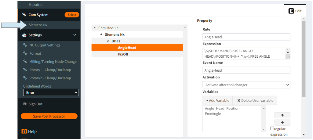
It is not a standard type of UDE. It is a custom UDE. Custom UDEs are UDEs that need to be defined as shown in the below example in the CAM settings section of MANUSpost Developer. In this UDE definition, the “Variables”, and “Event” that will be affected by this UDE should also be defined.
What is it used for?
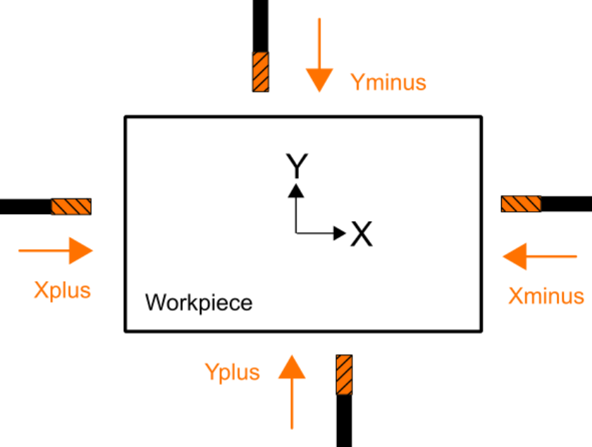
Angular tools are special “L” shaped tools used to machine areas that cannot be machined by standard cutting tools.
When adjusting the UDE to define the angular tools, the orientation direction of the angular tool (angular head position) at zero position (spindle oriented position) must be entered correctly either as +X,-X,+Y or -Y.
Important Note: Care should be taken while entering the angular tool position. For example, if the tip of the tool looks towards the +X direction of the machine axis, then +X should be entered as the angular tool orientation.
In standard use, there is no need to define the value of the “Free Angle” variable. “Free Angle” is only used in a special case which is explained below:
Special Case: When the direction of the angular tool is the same as the rotation axis vector of “Rotary Axis 1 (tilting/nutating axis)” . In this case, “Rotary Axis 1” can be positioned at any angle (there are infinite alternatives), and therefore the user is asked to define the “Free Angle” value to overcome this problem. In this case, the “Free Angle” value is directly used as the value of “Rotary Axis 1”.
How to deactivate it?
Normally, once this UDE is activated, it affects all subsequent operations.
There is no standard deactivation code for this UDE. Depending on the usage scenario, it can be deactivated by writing a “Script” defined by the user at the end of the operation.
To deactivate it, the original tool vector direction of the CNC machine must be redefined in the “SetToolReferenceOrientation” method within the “Script”. The standard tool vector in CNC machines is generally (0,0,1).
What Does it Affect/Change Inside MANUSpost Developer?
When this UDE is activated, no standard variables or events in MANUSpost Developer are affected. Only “Custom Variables” and “Custom Events” created by the user will be affected by this UDE.
The UDE is activated within a script defined in an “Event”. In this script, you should use the “SetToolReferenceOrientation” method to activeta this UDE. Depending on the selected angle head orientation (ANGLE HEAD/POSITION=+X,-X,+Y,-Y), a reference tool vector assignment should be made within this method.
When entering the tool vector information into “SetToolReferenceOrientation”, care should be taken. For example, if the tool tip is in the “+X” direction with respect to the machine axis, the vector in this method should be entered as (-1,0,0).