Angle Head
Examples of expressions that should be written within the Hypermill, “Manual NC” operation:
ANGLE HEAD/POSITION=@,FREE ANGLE=@
After adding these expressions in Hypermill, the following expression will be added in the created
POF file.
1: cfg(*LITERAL_1 BTC:ANGLE HEAD/POSITION=@,FREE ANGLE=@)
Type of UDE:
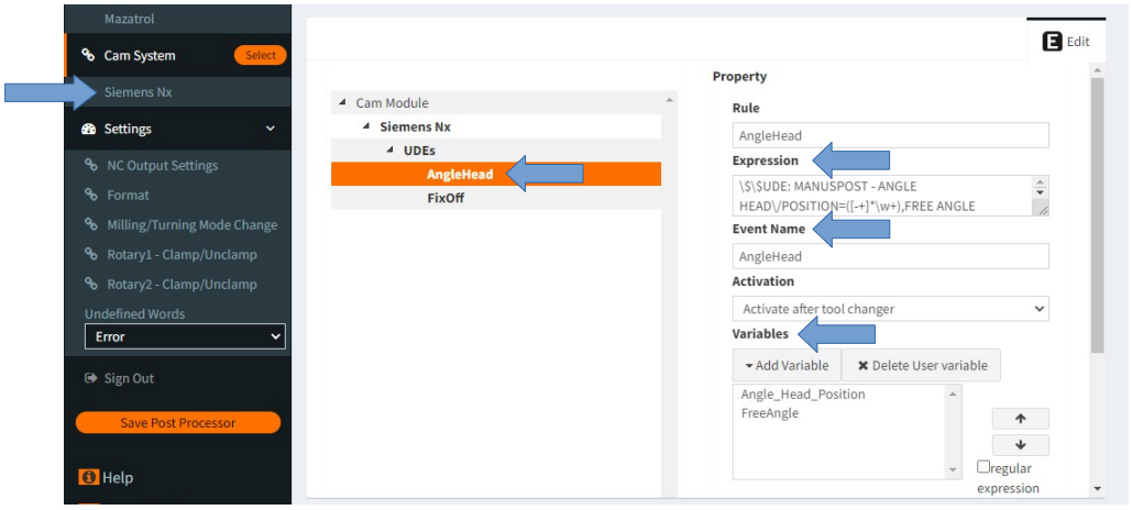
It is not a standard type UDE. It is a Custom (user defined) UDE. In order to activate this UDE, a
UDE must be defined in the CAM settings section of MANUSpost Developer. Within this UDE
definition, “Variable”, “Event” and “Script” that will be affected by this UDE should also be
defined.
What Is It Used For?:
Angle heads are special “L” shaped heads used to machine the places where the CNC machine
cannot provide machining with its own kinematics.
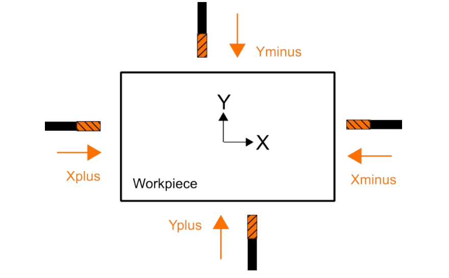
In order to define the angle heads correctly, when selecting the UDE, the clamping direction (+X,-
X,+Y,-Y) of the angle head at the zero position must be entered correctly, because the angle head
Note That: Care should be taken when entering the clamping direction information. For example,
+X must be entered as the clamping direction when the tool tip faces the + direction of the X axis
angle to be machined will be calculated according to this clamping direction.
In standard usage, the “Free Angle” variable value does not need to be defined. “Free Angle” is only
used in a special case. This special case:
-It is the case where the tool direction of the clameped angled head with the rotation vector of the
“Rotating Axis 1” (tilting/nutating axis) is the same, it coincides. In this case, “Rotary Axis 1” can
be positioned in infinite alternatives, to overcome this problem, the user is asked to define the “Free
Angle” value, and the “Free Angle” value is directly used as the “Rotary Axis 1” value.
How to Deactive?:
Normally, once this UDE is activated, it affects all subsequent operations.
This UDE has no standard deactivation code. According to the usage scenario, it is deactivated by
writing a “Script” defined by the user at the end of the operation or in an “Event” requested by the
user.
To deactivate it, the original tool vector clamping direction of the CNC machine must be defined in
the “SetToolReferenceOrientation” method in the “Script”. In CNC machines, the standard tool
vector is generally (0,0,1).
What Affects/Changes in MANUSpost Developer:
When this UDE is activated, any standard Variable or standard Event is not affected in MANUSpost
Developer. Only user-created “Custom Variables” and user-created Events will be affected by this
UDE.
This UDE is activated by using the “SetToolReferenceOrientation” method in a “Script” to be
defined in the “Event”. Depending on the clamping direction selected in this method (ANGLE
HEAD/POSITION=+X,-X,+Y,-Y), reference tool vector assignment should be made.
Note That: Care should be taken when entering the tool vector information into the
“SetToolReferenceOrientation”. For example, if the tool tip is in the “+X” direction relative to the
machine axis direction, the vector in this method should be entered as (-1,0,0).