Using UDEs
How to Add PP Instruction in Catia?
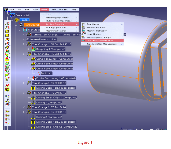
When you want to add a PP Instruction in Catia, it can be added using the “Post Processor Instruction” button or, if the button is not on the screen, with the “Insert > Auxilliary Operations > Post Processor Instruction” option as shown in Picture 1. PP Instruction will appear in the product tree like an operation, and then it can be moved from the product tree to whichever operation it wants to precede.
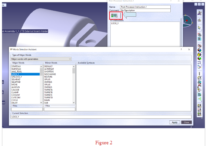
Afterwards, when you click on the button shown with the blue arrow in the window that opens, a second window will open where Major and Minor words can be added. The desired Post Processor Instruction is added from this window and saved.
1.Rotate Table
Standart PP Instructions Used in Catia
Type of PP Instruction:
It is a standard type PP insturction. In standard usage, there is no need to make an extra definition in MANUSpost developer to activate this PP insturction. However, if desired, UDE can be defined in the CAM settings section of MANUSpost developer (can also be defined as “Custom UDE”). In this case, the user can make extra customizations in this PP insturction, create and use “Event”, “Script”, “Command” connected to the PP insturction.
What Is It Used For?:
It is used to position the rotary table at an angle different from the zero position when a limit problem occurs in the X or Y axis in a 3-axis milling operation. With this UDE, the rotary table is rotated to the appropriate angle and the machining is performed within the limits of the machine.
How to Deactivate?
Once this UDE is activated, it becomes active for all subsequent 3-axis operations. In other words, all 3-axis operations after this UDE are machining in the rotary table angle defined in this UDE.
Therefore, in order to cancel this UDE, this UDE must be redefined with zero degree angle value at the beginning of the operation that is requested to be canceled as follows.
Rotabl 0
In the above example, if another angle is defined instead of zero as the rotate table angle value, the UDE remains active with the new angle value. In the next 3 axis operations, the rotate table angle value becomes the value defined in the new UDE.
What Affects/Changes in MANUSpost Developer:
It updates the C axis value, that is, “Var.Coordinate.RotaryAxis1” or “Var.Coordinate.RotaryAxis2” according to kinematics, with the angle value defined in the UDE.
2. Lock Axis
LOCK_Y
Type of PP Instruction:
It is a standard type UDE. In standard usage, there is no need to make an extra definition in MANUSpost developer to activate this UDE. However, if desired, UDE can be defined in the CAM settings section of MANUSpost developer (can also be defined as “Custom UDE”). In this case, the user can make extra customizations in this UDE, create and use “Event”, “Script”, “Command” connected to the UDE.
What Is It Used For?:
It is the UDE that is used to activate the Polar mode, and with this UDE one of the linear axes (usually the Y-axis) is locked (or deactivated), allowing the machining to be processed using the other linear axis (X-axis) and the rotary table C-axis.
Polar mode is a special mode used only in 3-axis milling operations.
This mode is activated when motion limits prevent machining in the machine X and/or Y axes.
Polar mode is a very common mode in mill-turn machines.
When this mod is activated:
Y axis is automatically disabled in mill-turn machines, machining is performed by using +X and C axis instead of Y axis, that is, by continuously rotating the part in C axis. Mill-turn machines usually have a command that activates this mode ( G12.1 / G112 / TRASNMIT etc.)
Although there is no special command that activates this mode on milling machines, this mode can also be used in 5-axis milling machines. Thanks to a special structure called “Parametric Polar Mode”, MANUSpost Developer allows you to use polar mode in your multi-axis milling machines. When you use it on milling machines, you can also choose to lock the X axis instead of Y and manage the process from the Developer kinematics settings. When one axis is locked, the operation is performed using the other linear axis and the C axis.
In 5-axis milling machines, the locked axis is selected as the axis with short mobility, that is, the axis with the axis limit problem.
In case of limited mobility of both X and Y axis in 5-axis milling machines, MANUSpost Developer has the flexibility to enable any diagonal axis with scripts and variables.
Since the MCS in 5-axis milling machines is mostly not in the center of the table, your CNC machine must have TCPC feature to perform this operation, a parametric solution must be produced for the machines without TCPC feature.
Some of the mill-turn machines may not have Polar codes (G12.1 / G112 / TRANSMIT) or their use may be problematic. In such cases, you can use the special parametric polar mode of MANUSpost Developer.
You can watch the related videos to get detailed information about the use of polar mode and parametric polar mode in milling and mill-turn machines.
How to Deactivate?:
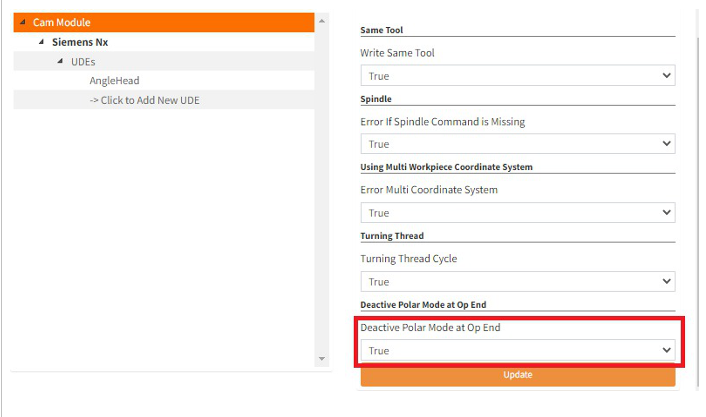
When this ude is activated, it only affects the subsequent operation. It is automatically deactivated after the operation. If you want this PP instruction to remain active until the end of the program after it is defined, select “Deactive Polar Mode at Op End” as “False” in CAM settings in MANUSpost developer as shown in the picture below.
What Affects/Changes in MANUSpost Developer:
When this UDE is activated, the “VAR.State.OpPolar” variable becomes active (True) and the “OpPolar” operation type is added to the operation tree and the kinematics and “Commands” that are desired to work in this operation type are defined here.
3. Select Spindle
SELSPIND/MAIN
SELSPIND/SUB
Type of PP Instruction:
It is a standard type UDE. In standard usage, there is no need to make an extra definition in MANUSpost developer to activate this UDE. However, if desired, UDE can be defined in the CAM settings section of MANUSpost developer (can also be defined as “Custom UDE”). In this case, the user can make extra customizations in this UDE, create and use “Event”, “Script”, “Command” connected to the UDE. In this case, the standard UDE will be deactivated and the custom UDE will be activated.
What Is It Used For?:
It is used in machines with subspindle and single turret. It is used to determine which spindle is active and cutting in this type of machines. In case UDE is not added, MAIN spindle is active by default.
How to Deactivate?:
Once the UDE is activated, it will affect all subsequent operations. If a change is desired, the same UDE should be activated by selecting the other alternative. In other words, if “Main” is selected, “Sub”, if “Sub” is selected, “Main” is selected, the UDE is deactivated.
What Affects/Changes in MANUSpost Developer:
When this UDE is activated, the values of the variables “VAR.State.OpMainSpindle” and “VAR.State.OpSubSpindle” are updated automatically.
When “Main” is selected, the “VAR.State.OpMainSpindle” variable will take the value “True” and the “VAR.State.OpSubSpindle” variable will get the value “False”.
When “Sub” is selected, the “VAR.State.OpMainSpindle” variable will take the value “False” and the “VAR.State.OpSubSpindle” variable will get the value “True”.
4. Five Axis Start
START5AX=DEFAULT
START5AX=ALTERNAT
Type of PP Instruction:
It is a standard type UDE. In standard usage, there is no need to make an extra definition in MANUSpost developer to activate this UDE. However, if desired, UDE can be defined in the CAM settings section of MANUSpost developer (can also be defined as “Custom UDE”). In this case, the user can make extra customizations in this UDE, create and use “Event”, “Script”, “Command” connected to the UDE.
What Is It Used For?:
In 5-axis machines, there are usually two alternative machining angles depending on the machine rotary axis limit state in indexed and simultaneous operations.
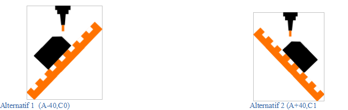
The post processor will normally select the first motion position at the beginning of the operations to process on the preferred (minus/plus) side on the MANUSpost Developer kinematics definition page. If the users wants to process in the other alternative, they should activate the alternative option with this UDE.
How to Deactivate?:
Once “Alternate” is activated with this UDE, it affects all subsequent operations. To switch to the default side again, “Default” must be selected with the same UDE. The “Default” selection should be defined just above the operation for which you want to cancel the “Alternate” selection.
What Affects/Changes in MANUSpost Developer:
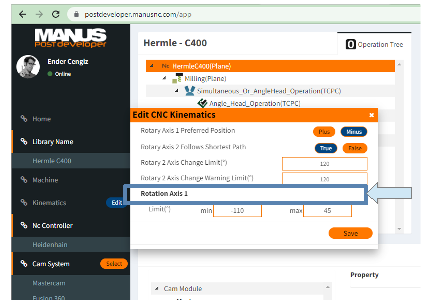
When this UDE is activated, no standard variables are affected in MANUSpost Developer. It will only affect the “Rotary Axis 1 Preffered Pos” selection defined in the kinematics page.
5. Five Axis Rapid
RAPID5AX=SHORTDIS RAPID5AX=NOCHANGE RAPID5AX=RESTORE
Type of PP Instruction:
It is a standard type UDE. In standard usage, there is no need to make an extra definition in MANUSpost developer to activate this UDE. However, if desired, UDE can be defined in the CAM settings section of MANUSpost developer (can also be defined as “Custom UDE”). In this case, the user can make extra customizations in this UDE, create and use “Event”, “Script”, “Command” connected to the UDE. In this case, the standard UDE will be deactivated and the custom UDE will be activated.
What Is It Used For?:
It is similar to use with the “Five Axis Start” UDE. The main difference is that the “Five Axis Start” UDE is used to determine the direction (plus/minus) of the “Rotating Axis 1” (tilting/nutating axis) during the first motion at the beginning of the operation, while the “Five Axis Rapid” UDE is used to decide the direction (plus/minus) of “Rotary Axis 1” similarly in RAPID motions within the operation, except for the operation start.
According to the option determined by UDE, the direction (plus/minus) of RAPID motions within the operation (except at the beginning of the operation) is controlled.
In order for this UDE to be active, there must be RAPID motions at the end of the positioning movements during operation changes. Because this algorithm of MANUSpost only affects the middle RAPID motions except the first and last when at least three RAPID motions are side by side.
When the “SHORTDIS” option is selected, this RAPID motion in between is positioned with the rotary axis shortest path algorithm.
The direction of RAPID motion does not change when the “NOCHANGE” option is selected. If the previous rotary axis position is in “Plus”, it remains in the “Plus” position, and in “Minus” it remains in the “Minus” position.
When the “RESTORE” option is selected, the RAPID motion positions itself in the direction defined by the “Five Axis Start” UDE. “Rotating Axis 1” (tilting/nutating axis) stays in the default position if “Default” direction is defined in “Five Axis Start” UDE, and in alternative position if “Alternate” is defined.
How to Deactivate?:
When one of the options is activated with this UDE, that option is defined to remain active until it is changed.
Once this UDE is activated, it affects all subsequent operations. To cancel the active UDE, the same UDE must be redefined by selecting another option just above the operation to be canceled.
What Affects/Changes in MANUSpost Developer:
When this UDE is activated, there is no change in any variable that can be accessed by end users in MANUSpost Developer. This UDE affects algorithms for calculating rotary axis values.
6.Synchronization
Type of PP Instruction:
It is a standard type UDE. In standard usage, there is no need to make an extra definition in MANUSpost developer to activate this UDE.
What Is It Used For:
It is used in multi-turret (multi-channel) machines, to ensure that each channel (turret) works in the desired order or to operate together.
How to Deactive?:
It is effective on the line it is printed on. Therefore, it does not need to be deactivated. When this UDE is activated, “Synchronization Number” is assigned in the CLS file before the operation in which it is activated.
What Affects/Changes in MANUSpost Developer:
This UDE defines the value of the “VAR.Turret.SynchronizationNumber” variable in MANUSpost Developer and the “Word” created from this variable is used in the desired “Command”, and the desired synchronization number is printed in the NC program at the desired position.
7. COOLANT
Below are the cooling options supported by MANUSpost Developer.
COOLNT/FLOOD COOLNT/THRU COOLNT/AIR COOLNT/MIST COOLNT/OFF
If you want to use a cooling option other than the types described above, you can do so by defining “Custom UDE”.
Type Of PP Instruction:
It is a standard type UDE. In standard usage, there is no need to make an extra definition in MANUSpost developer to activate this UDE. However, if desired, UDE can be defined in the CAM settings section of MANUSpost developer (can also be defined as “Custom UDE”). In this case, the user can make extra customizations in this UDE, create and use “Event”, “Script”, “Command” connected to the UDE.
What Is It Used For:
It is used to select the cooling type during the operation and then to activate and deactivate at the same time.
How to Deactive?:
It becomes active only in the line where it is defined and by activating the words “CoolantOn” or “CoolantOff”, the NC prints the relevant M commands to the program.
What Affects/Changes in MANUSpost Developer:
When this UDE is defined and coolant is selected (COOLNT/FLOOD, COOLNT/THRU etc.), the coolant is activated. Then, “Format Coolant On” command is activated in MANUSpost Developer and at the same time, the value of the “Var.Coolant.On” variable defined as standard is assigned.
In MANUSpost Developer, there is the “Word” “CoolantOn” created from the variable “Var.Coolant.On” and found as standard. By using this word in the “Format Coolant On” command, the relevant M command is printed to the NC program according to the selected cooling type.
When this UDE is used to cancel the coolant (COOLNT/OFF), the “Format Coolant Off” command is activated in MANUSpost Developer and at the same time, the value of the standard “Var.Coolant.Off” variable is assigned.
In MANUSpost Developer, there is the word “CoolantOff” created from the variable “Var.Coolant.Off” and found as standard. By using this word in the “Format Coolant Off” command, the relevant M command that cancels the coolant is printed to the NC program according to the selected cooling type.
8. STOP
Type Of PP Instruction:
It is a standard type UDE. In standard usage, there is no need to make an extra definition in MANUSpost developer to activate this UDE.
What Is It Used For:
It is used to activate the wait command in the NC program.
How to Deactive?:
It becomes active only in the line where it is defined and by activating the “Format Program Pause” command, the NC prints the relevant commands to the program.
What Affects/Changes in MANUSpost Developer:
It calls the “Format Program Pause” command in MANUSpost Developer and prints the statements attached in it to the NC code.
Commonly Used PP Instructions in Catia
1. Angle Head
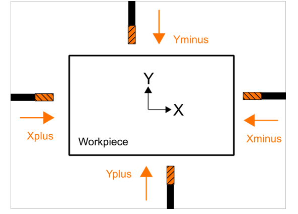
ANG_TOOL/XPLUS ANG_TOOL/XMINUS ANG_TOOL/YPLUS ANG_TOOL/YMINUS
Type Of PP Instruction:
It is not a standard type UDE. It is a Custom (user defined) UDE. In order to activate this UDE, a UDE must be defined in the CAM settings section of MANUSpost Developer. Within this UDE definition, “Variable”, “Event” and “Script” that will be affected by this UDE should also be defined.
What Is It Used For:
Angle heads are special “L” shaped heads used to machine the places where the CNC machine cannot provide machining with its own kinematics.
In order to define the angle heads correctly, when selecting the UDE, the clamping direction (+X,-X,+Y,-Y) of the angle head at the zero position must be entered correctly, because the angle head Note That: Care should be taken when entering the clamping direction information. For example, +X must be entered as the clamping direction when the tool tip faces the + direction of the X axis angle to be machined will be calculated according to this clamping direction.
In standard usage, the “Free Angle” variable value does not need to be defined. “Free Angle” is only used in a special case. This special case:
-It is the case where the tool direction of the clameped angled head with the rotation vector of the “Rotating Axis 1” (tilting/nutating axis) is the same, it coincides. In this case, “Rotary Axis 1” can be positioned in infinite alternatives, to overcome this problem, the user is asked to define the “Free Angle” value, and the “Free Angle” value is directly used as the “Rotary Axis 1” value.
How to Deactive?:
Normally, once this UDE is activated, it affects all subsequent operations.
This UDE has no standard deactivation code. According to the usage scenario, it is deactivated by writing a “Script” defined by the user at the end of the operation or in an “Event” requested by the user.
To deactivate it, the original tool vector clamping direction of the CNC machine must be defined in the “SetToolReferenceOrientation” method in the “Script”. In CNC machines, the standard tool vector is generally (0,0,1).
What Affects/Changes in MANUSpost Developer:
When this UDE is activated, any standard Variable or standard Event is not affected in MANUSpost Developer. Only user-created “Custom Variables” and user-created Events will be affected by this UDE.
This UDE is activated by using the “SetToolReferenceOrientation” method in a “Script” to be defined in the “Event”. Depending on the clamping direction selected in this method (ANGLE HEAD/POSITION=+X,-X,+Y,-Y), reference tool vector assignment should be made.
Note That: Care should be taken when entering the tool vector information into the “SetToolReferenceOrientation”. For example, if the tool tip is in the “+X” direction relative to the machine axis direction, the vector in this method should be entered as (-1,0,0).
2. Select Head , Select Spindle
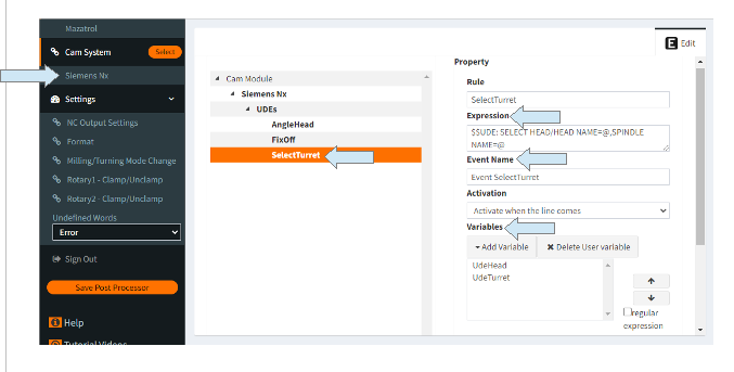
SELHEAD/TURRETA SELHEAD/TURRETB SELHEAD/TURRETC
Type Of PP Instruction:
It is not a standard type UDE. It is a Custom (user defined) UDE. In order to activate this UDE, a UDE must be defined in the CAM settings section of MANUSpost Developer. Within this UDE definition, “Variable”, “Event” and “Script” that will be affected by this UDE should also be defined.
What Is It Used For:
It is used for both “lower turret / upper turret” selection and “main spindle / sub spindle” selection in machines with multi turrets and sub spindles.
This UDE is used for “head” selection in milling machines with different types of head options, as it is mostly used on machines with multi turrets and sub spindles. The choice of “spindle” will not matter in such machines. It is sufficient to select only “head”.
How to Deactive?:
Once the UDE is activated, it will affect all subsequent operations. If it is desired to change the “turret/head” and “main/subspindle” selection in subsequent operations, this UDE must be redefined just above the operation to be changed.
What Affects/Changes in MANUSpost Developer:
The “Head Name” parameter, which is the first parameter of this UDE and used for turret/head selection, does not affect any standard Variable or standard Event in MANUSpost Developer. Only user-created “Custom Variables” and user-created Events will be affected by this UDE.
The second parameter of this UDE, the “Spindle Name” selection, behaves like the Standard UDE. After the selection of this parameter, the values of the “VAR.State.OpMainSpindle” and “VAR.State.OpSubSpindle” variables defined in MANUSpost Developer are updated automatically.
When “Main” is selected as the “Spindle” selection, the “VAR.State.OpMainSpindle” variable will take the value “True” and the “VAR.State.OpSubSpindle” variable will get the value “False”.
When “Sub” is selected as the “Spindle” selection, the “VAR.State.OpMainSpindle” variable will take the value “False” and the “VAR.State.OpSubSpindle” variable will take the value “True”.